
Latest Products
-
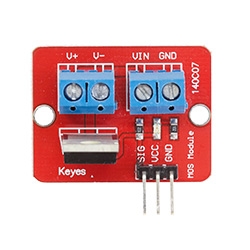 IRF520 MOS FET Driver Module ( Copy ) ( Copy )
4.64€
IRF520 MOS FET Driver Module ( Copy ) ( Copy )
4.64€ -
 180pcs M3 Nylon Spacers Screws Nuts Hexagon Studs Box Kit
8.33€
180pcs M3 Nylon Spacers Screws Nuts Hexagon Studs Box Kit
8.33€ -
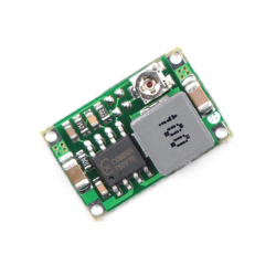 MINI360 3A MINI DC-DC STEP DOWN CONVERTER VOLT REGULATOR 5V-23V TO 3. 6V 9V 12V
2.62€
MINI360 3A MINI DC-DC STEP DOWN CONVERTER VOLT REGULATOR 5V-23V TO 3. 6V 9V 12V
2.62€ -
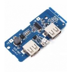 5V Power Bank circuit board
4.17€
5V Power Bank circuit board
4.17€ -
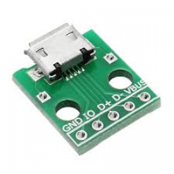 Micro Usb to Dip
2.96€
Micro Usb to Dip
2.96€ -
 ICS43432 I2S Digital Microphone
10.12€
ICS43432 I2S Digital Microphone
10.12€ -
 LED breakout module
4.17€
LED breakout module
4.17€ -
 Delay Trigger
2.98€
Delay Trigger
2.98€ -
 Adafruit I2S MEMS Microphone Breakout - SPH0645LM4H
10.12€
Adafruit I2S MEMS Microphone Breakout - SPH0645LM4H
10.12€ -
 VL53L0X V2 laser range distance sensor module
4.71€
VL53L0X V2 laser range distance sensor module
4.71€ -
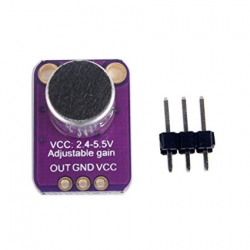 GY-4466 Professional MAX4466 High Precision Electret Microphone Amplifier with Adjustable Gain for Arduino
7.14€
GY-4466 Professional MAX4466 High Precision Electret Microphone Amplifier with Adjustable Gain for Arduino
7.14€ -
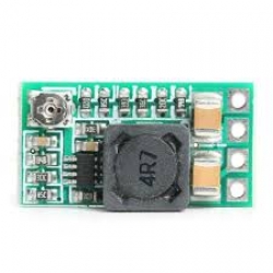 DC to DC HW613 step down
2.38€
DC to DC HW613 step down
2.38€ -
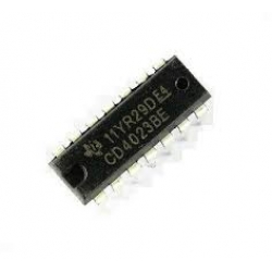 Nand gate
1.19€
Nand gate
1.19€ -
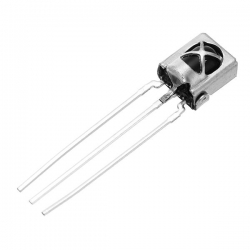 38KHz Infrared IR Receiver Sensor Module Geekcreit for Arduino ( Copy )
1.79€
38KHz Infrared IR Receiver Sensor Module Geekcreit for Arduino ( Copy )
1.79€ -
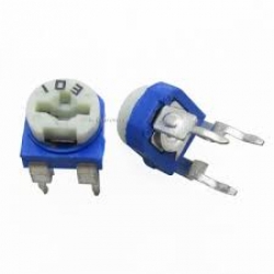 Potentiometer 10k Ohms
0.36€
Potentiometer 10k Ohms
0.36€ -
 OP-AMP
1.19€
OP-AMP
1.19€ -
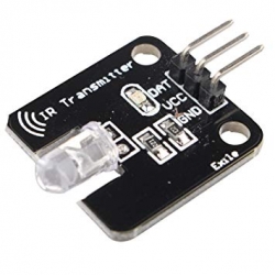 38KHz Infrared IR Transmitter Sensor Module Geekcreit for Arduino
2.38€
38KHz Infrared IR Transmitter Sensor Module Geekcreit for Arduino
2.38€ -
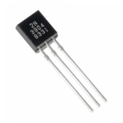 2N3904 transistor
1.19€
2N3904 transistor
1.19€ -
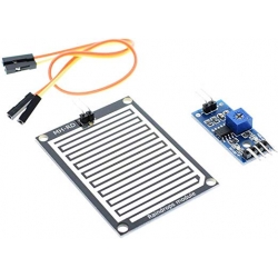 Raindrops Detection Sensor Module Compatible with Arduino
8.33€
Raindrops Detection Sensor Module Compatible with Arduino
8.33€ -
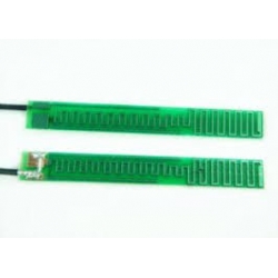 PCB LoRa antenna
5.36€
PCB LoRa antenna
5.36€ -
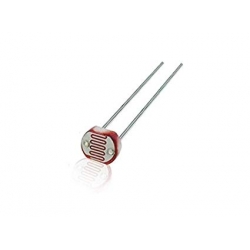 Photoresistor Photo Light Sensitive Resistor Light Dependent Resistor
1.19€
Photoresistor Photo Light Sensitive Resistor Light Dependent Resistor
1.19€ -
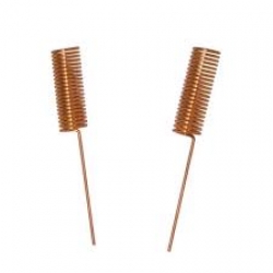 helical coil antenna
5.36€
helical coil antenna
5.36€ -
 ARCELI DC to DC step down
2.98€
ARCELI DC to DC step down
2.98€ -
 22402A-18 protoboard one side 5X7 cm
3.45€
22402A-18 protoboard one side 5X7 cm
3.45€ -
22402A-18 protoboard two sided 5x7 cm
3.45€
-
22402A-18 protoboard two sided 4x6 cm
3.45€
-
 22402A-17 protoboard two sided 2x8 cm
3.45€
22402A-17 protoboard two sided 2x8 cm
3.45€ -
22402A-17 protoboard two sided 3x7 cm
3.45€
-
 WHITE LED's 5mm
0.36€
WHITE LED's 5mm
0.36€ -
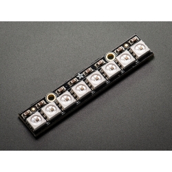 NeoPixel Stick - 8 x 5050 RGB LED with Integrated Drivers
5.95€
NeoPixel Stick - 8 x 5050 RGB LED with Integrated Drivers
5.95€ -
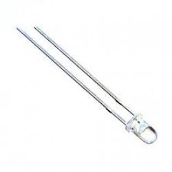 WHITE LED's 3mm
0.30€
WHITE LED's 3mm
0.30€ -
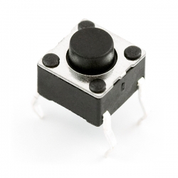 mini push button switch 4 pin ( Copy )
0.60€
mini push button switch 4 pin ( Copy )
0.60€ -
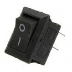 rocket switch 2 pin
0.60€
rocket switch 2 pin
0.60€ -
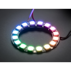 New Led Ring 16x 5050 RGB LED Board with Integrated Drivers Module Geekcreit for Arduino - products that work with official Arduino boards
7.14€
New Led Ring 16x 5050 RGB LED Board with Integrated Drivers Module Geekcreit for Arduino - products that work with official Arduino boards
7.14€ -
 Lot Limit switch 3 pin
0.60€
Lot Limit switch 3 pin
0.60€ -
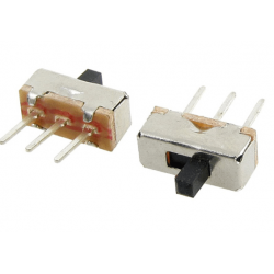 Slide switch 3 pin
0.60€
Slide switch 3 pin
0.60€
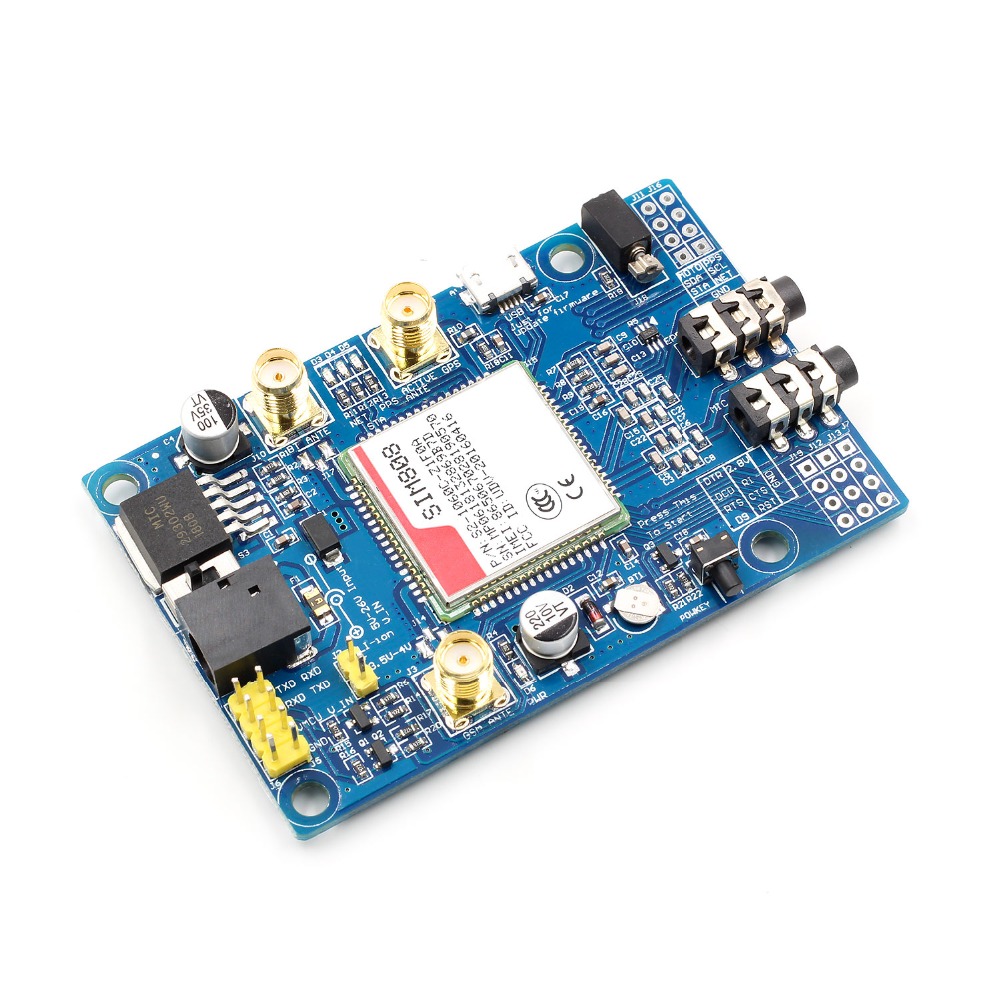

SIM808 Module GSM GPRS GPS Development Board SMA With GPS Antenna For Arduino
33.32€
1.Three power input interface: DC044 interface and V_IN and a lithium battery interface.
Note that: The range of DC044 and the V_IN pin voltage input is 5 - 26V, when use the 5V as the power, be sure that the power supply can provide 2A current. The range of voltage of Lithium battery input power is 3.5 - 4.2V.
2. Switch: It is used to open / close the input power supply for the module. When in use, please confirm the toggle switched to the OPEN state (near the board inside).
3. SMA antenna interface: there is a GSM antenna interface, a GPS antenna interface onboard and a BT antenna interface.
4. Start button: When the board is power on, the LED (PWR) will light up. After a long press (about 2 second) on this button, the other three LEDs will be light. And one of them starts to flash; this suggests that SIM808 is beginning to work now. When the power supply, GSM and GPS antenna and SIM card are connected to the module correctly, the LED will be flash slowly (3Second de 1second light), that indicates that the module is registered to the network, and you can make a call or do something else.
5. TTL serial interface: a TTL level interface. Notice that: The pin of VMCU is used to control the high level of TTL UART, so as to realize to match between 1.25V/3.3V /5V systems. For example, if you want to use the 51 MCU to control this board, the pin of VMCU should be connected the DC5V. And if use the STM32 MCU, the pin of VMCU should be connected the DC3.3V. The pins of RXD is the RXD of SIM808 and the pins of TXD is the TXD of SIM808. The pin of V_IN can connect the Power, the function of this pin has the same function of DC044.
6. USB interface: This interface is just use to update the firmware of SIM808 module.
Operation Description:
1. Preparation:
SIM808 SHIELD
DC9V adapter
USB-TTL module or other tools.
PC software
2. Hardware configurations
2.1 Connect the USB-TTL to the UART interface
USB-TTL SIM808
TXD RXD
RXD TXD
GND GND
2.2 Insert the valid SIM card to the SIMCARD holder.
2.3 Connect the GPS antenna and GSM antenna to the board
Connect the power adapter to the DC044 Interface
2.4 Change the switch
2.6 Press the POWKEY button for 2 second, the SIM808 module will work and the other 3 LEDs will light.
Package Included:
1 X SIM808 Moudle
1 X GSM Antenna
1 X GPS Antenna